37+ block diagram examples control system
Start at the OL poles end at the OL zeros or infinity. Webb ESE 499 3 Block Diagrams In the introductory section we saw examples of block diagrams to represent systems eg.

Amazon Com 3000w Solar Hybrid Inverter 24v Dc To 110v Ac Pure Sine Wave Off Grid Inverter All In One With 60amp Mppt Controller Max 3000w 100v Pv Input For 24v Batteries Everything
Simplify the block diagram then obtain the close-loop transfer function C.
. Lets use the Electronics Block Diagrams. Y s G s X s Similarly block for each element of control. Let us simplify reduce this block diagram using the block diagram reduction rules.
Use Rule 2 for blocks G 3 and G 4. Use Createlys easy online diagram editor to edit this diagram collaborate with others and export results to multiple image formats. Analog systems are things like cruise control on your car where the inputs and outputs are continuous variables that can make small changes.
A water tap can be taken as simple and best example. A block diagram representation in which there is only one forward and feedback block along with a single summing point and take-off point is the simplest form of closed-loop control. Block diagrams consist of Blocks these represent.
These blocks are joined by lines to display the relationship between. Then we will divide them into sections or. The examples will be MCQ.
You can edit this template. Reduce the system to a single transfer function. A water tap can be taken as simple and best example of a control system.
You can have digital controls. Here the flow of water ie the output is mechanically controlled by the movement of valve ie. Ad Templates Tools To Make Block Diagrams.
A block diagram is a drawing illustration of a system whose major parts or components are represented by blocks. The output Y s is the product of input X s and transfer function G s of the block and is given by equation. Here we will discuss the examples related to the block diagram reduction signal flow graph masons gain formula and basic concepts of the control system.
Block diagram shown in Figure 3-44. Block Diagram in control systems. Block Diagram Control System.
Functional Software Electrical etc. It is used to show so that we can understand the design complete circuits easily. Any system can be described by a set of differential equations or it can be represented by the schematic diagram that contains all the components.
Root Locus Rules for plotting root loci Get the characteristic equation in the following form. Step 1 Use Rule 1 for blocks G 1 and G 2. Block Diagram in control systems.
Figure 3-46 Block diagram of a system.

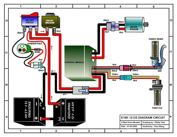
Razor E100 Electric Scooter Parts Electricscooterparts Com
1

Block Diagrams Block Diagram Diagram Process Flow Diagram
2
2
1

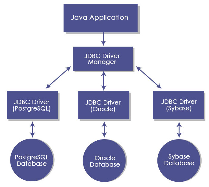
Jdbc Architecture Interfaces Types Components Architecture

Block Diagram Of A Dcs System Automation Distributed Control System Process Control Programmable Logic Controllers

Block Diagram Of Closed Loop Control System System Control System Transfer Function

Block Diagram Reduction Problem Solving Block Diagram Flow Chart
2

Biodegradable Magnetic Molecularly Imprinted Anticancer Drug Carrier For The Targeted Delivery Of Docetaxel Acs Omega

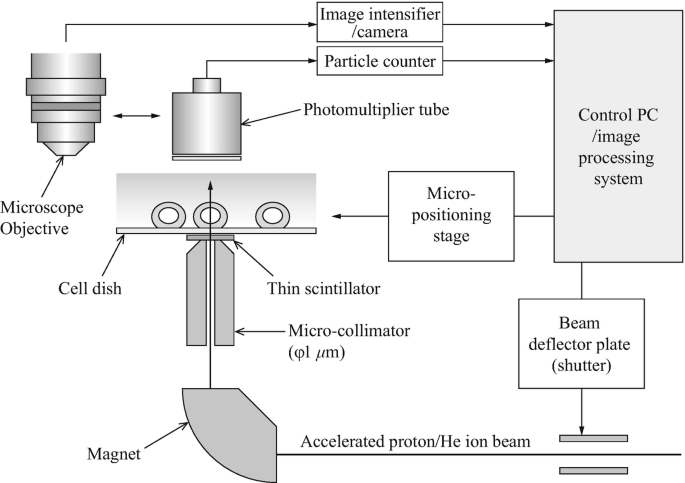
Experiments Of Local Irradiation Of Cells With Heavy Ion Microbeams Springerlink

Gateway Load Balancer Aws Introduction Valtix
2
1

Block Diagram Of Engine Control Unit Engine Control Unit Block Diagram Diagram